


Most people in the adhesives and sealants industry are aware of viscosity and realize that it characterizes the way a material will flow. More technically speaking, viscosity refers to a material’s resistance to flow; it can be measured in various ways, depending on the nature of the application. An evaluation of how the material is being processed in manufacturing or how the end user will try to apply it is the basis for determining the type of viscosity test that should be performed.
Measuring Caulk Viscosity
Imagine a caulk gun. The squeezing force required to expel the material out of the nozzle is important to know. If the caulk is not sufficiently viscous, too much will come out and some will be wasted. In addition, the caulk that does come out probably won’t hold its position on the substrate. Should the caulk be too viscous, it may not come out at all. In either case, the material is rejected and the customer is unhappy.
Quality control (QC) in manufacturing requires that a test method be established to predict this type of problem before it happens. The way to simulate the gun’s squeezing action on the caulk is through an extrusion test. An instrument called a texture analyzer—with an extrusion cell—is ideally suited for this type of test. This type of instrument, also sometimes called a universal tester, essentially applies compression or tension to a material. In this case, the instrument simulates the process of pushing the material through a tube and out of the nozzle.
During this type of test, the extrusion cell is filled with the sample material. A small circular opening in the bottom of the cell represents the nozzle diameter through which the caulk material will be expelled. A disc-shaped plunger is brought down into contact with the material in the top of the cell. The test method is to move the plunger at a defined speed down into the cell. The material is expelled out of the opening in the cell bottom. A load sensor in the instrument monitors the resistive force experienced by the plunger as it pushes downward into the material. The key data recorded is the force as a function of time and distance, which provides a complete characterization of the squeezing action required to extrude the caulk out of the gun.
Technically speaking, this type of instrument is not a viscometer, but it nonetheless gives a measure of the caulk’s viscosity. The output parameter is the force required to extrude the caulk. This correlates to how much work the user will perform to get the caulk out of the gun. It is crucial to select a test method that correctly characterizes what is happening to the material. Since many adhesive and sealant materials are applied from a gun of some type, the texture analyzer becomes a relevant tool to perform the tests.
Shear Rate
One key concept that is often not understood is that a material’s viscosity is not a single point measurement; it typically depends on a number of factors. Take the previous example of the caulk. The speed at which the plunger pushes into the material will have a direct effect on the force resistance that is measured. The faster the plunger moves into the caulk, the higher the force that will be measured. Therefore, the rate of shearing action on the caulk is greater and may result in different viscosity values.
The primary challenge to understanding viscosity is to recognize that shear rate plays a key role in determining the resistance to flow. As previously stated, it is necessary to think about how the material will be processed or handled when in use. The shearing action is what should be analyzed in order to arrive at a relevant test method for measuring viscosity.
For liquid glues, the use of a rotational viscometer running at different speeds simulates what is happening to the material when stored in a bottle or applied to a substrate. The shearing action of the glue sloshing around in the bottle is relatively low, while the application process for placing the glue can be rather high. Once the glue is applied, the shearing action is again pretty low, because only gravity is causing it to spread out farther. This assessment of how the glue is used leads to the selection of the appropriate viscometer.
Dynamic Viscosity
Rotational viscometers are perhaps the most popular tool for measuring viscosity. The spindle, when inserted into the test material, rotates at various discrete speeds, thereby shearing the material at precise shear rates. The viscometer measures the amount of torque resistance imparted by the material against the rotating spindle at each speed. The torque measurement is quantified as the shear stress acting on that portion of the spindle surface that is immersed in the material. The measured parameter (torque) and the control parameter (spindle speed) are combined into an equation that defines dynamic viscosity as the ratio of shear stress to shear rate:
Dynamic Viscosity = Shear Stress/Shear Rate
Centipoise (cP) is the unit of measurement most often used in North and South America to quantify rotational viscosity; the milli-Pascal second (mPa.s) is typically used outside the Americas (1 cP=1 mPa.s). This one-for-one equivalency minimizes potential problems when comparing data between multinational manufacturing plants.
Distilled water is the benchmark reference for comparing the viscosity of all other materials. The National Institute of Standards and Technology (NIST) specifies that the viscosity of water is 1cP when measured with a capillary viscometer at 20°C.
The choice of spindle for shearing the material is dictated by its general flow behavior and historical precedence for viscosity tests. The standard disc-type spindle is the most often used because it has been in existence for over 75 years. Various other spindle geometries can also be used, depending on the amount of sample that is available and how viscous the material is (see Figure 1). Available geometries include cylinder, cone, T-bar and vane. Coaxial cylinder (cylindrical spindle in a cylindrical chamber) and cone/plate are chosen when the shearing action requires a defined shear rate.
Determining Shear Rate
The choice of shear rate is determined by analyzing how the material is processed. Imagine that the material is sandwiched between two plates separated by a fixed distance. If the bottom plate is kept stationary and the top plate moves at a defined velocity, then the shear rate is the ratio of the moving plate velocity (V) to the distance separating the plates (X):
Shear Rate = V/X
The reciprocal second (s-1) is the unit of measurement for shear rate. This approach to quantifying shear rate assumes that the fluid behaves in a uniform (laminar) way, as shown by the arrows in Figure 2. The layers of molecules in the material remain together in the same plane and slide over each other in such a way that the closer they are to the moving plate, the faster each layer moves.
The relevant shear rate(s) for an application can easily be computed by applying the above equation. When placing adhesive on a substrate with a scraper, the substrate and the scraper represent the two plates. To lay down a bead of adhesive 1 mm thick in an automated operation where the substrate is moving at 50 cm/sec, the shear rate is 500 sec-1. This becomes one of the shear rates that should be used in a QC test.
Flow Behavior
With the above concept concerning relevant shear rates in mind, it is possible to see more clearly that viscosity may not be a single number for a given material. The idea is to test a material with a viscometer at different rotational speeds (i.e., different shear rates) and see what viscosity values are measured.
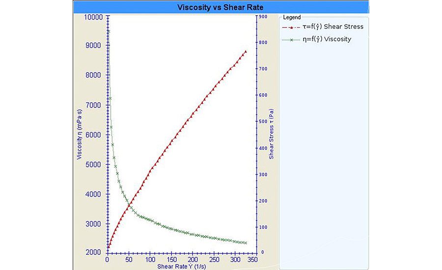
The most common flow behavior is called pseudoplastic (or shear thinning), where a material’s viscosity decreases with increasing shear rate. Figure 3 is a rheogram that illustrates the behavior for a liquid adhesive tested at relatively low shear rates. Most adhesive and sealant materials exhibit pseudoplastic behavior; for example, autobody fillers are highly viscous materials with obvious pseudoplastic flow. Figure 4 shows that the apparent viscosity decreases dramatically as the shear rate increases to 100 s-1, then decreases more gradually above that shear rate.
A related issue that affects measured viscosity values is the length of time the shearing action is applied to the material. When a material is sheared at a constant rate and the measured viscosity decreases with time, the flow behavior is called thixotropic. Many adhesive and sealant materials exhibit thixotropic behavior; it is important to consider whether the viscosity recovers to its original value once the shearing action stops, and whether this type of behavior is wanted or expected. Once the bead of glue has been placed on the substrate, does the viscosity recover so that the material holds its shape and doesn’t spread out like water on a flat surface?
Temperature is yet another parameter to consider when measuring viscosity. As temperature increases, most materials exhibit a decrease in viscosity. Therefore, the temperature at which the QC check is performed should be defined in order to ensure consistent results. When new adhesives or sealants are formulated, it is customary to perform a temperature profile test. The material is tested at a constant shear rate while the temperature cycles between a minimum and maximum value. The resulting graph provides QC with a reference chart for expected viscosity values at different temperatures.
Yield Stress
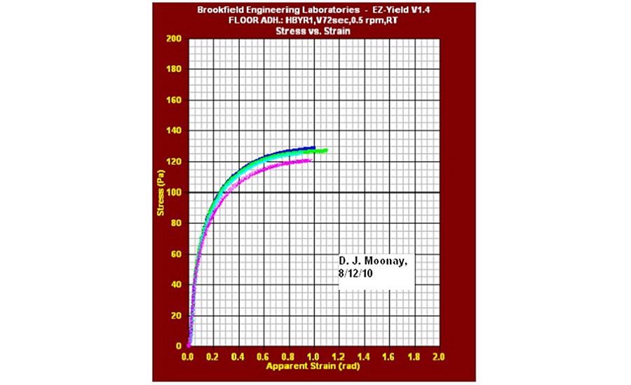
Some users may wish to apply an adhesive to a particular area and have it stay put (hold its position) until pushed with a blade or trowel. Perhaps a second piece is then pressed into place on the adhesive layer. Flooring adhesive is an example of this type of application. The property corresponding to that behavior is called yield stress and it represents the amount of applied force at which a solid material begins to flow like a liquid. The yield strain is the degree of sample deformation that results from the applied yield stress. These two values appear on a stress-strain curve at the yield point.
One easy method for testing the yield stress of adhesive/sealant materials is to use a rotational viscometer running at a very low speed (e.g., 0.01-1 rpm). The instrument uses a vane spindle immersed in the material and running at a constant speed. The calibrated spring inside the viscometer winds up, applying increasing force to the vane spindle, but the sample resists moving. The sample then begins to deform slightly, until its structure breaks down and it starts to flow. The measured torque value is converted into a stress value (in Pascals or dyne-cm), and this defines the yield stress for the material.
Figure 5 shows the type of flow curves that can be generated when measuring yield stress with a viscometer. In this case, the instrument is specifically configured to measure yield stress and present the data in the appropriate scientific units for this parameter. Four curves show good repeatability for the yield stress of this particular material. The test is easy to run and typically takes less than one minute.
The controlled stress rheometer is an alternative instrument for measuring yield stress. If the quantity of material available for testing is limited, the cone/plate system is the best choice. Practically speaking, the cone/plate system is also ideal if temperature control is required; the time required to bring the sample to temperature is minimized when using cone/plate. The test method is to run a shear ramp in which increasing torque is applied to the spindle until it begins to rotate. The torque value where the rotation of the spindle commences is the yield stress.
Controlled stress rheometers are more expensive instruments than benchtop viscometers. If the budget allows for the controlled stress rheometer, this is the preferred approach, because the instrument can also perform the viscosity flow curve test and check for pseudoplastic behavior, thixotropy, and recovery of material after being sheared.
Curing Test
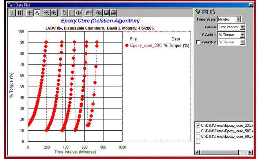
One final thought on viscosity testing applies to materials like epoxies, where viscosity builds with time as the adhesive gains strength. The objective is to know the endpoint of the reaction (i.e., the final strength of the epoxy and how long it takes to get there). A curing algorithm can be used with a standard digital viscometer that is equipped with a special program that enables the instrument to change speeds automatically.
The viscometer measures viscosity continuously as the spindle rotates initially at a high speed (e.g., 50 or 100 rpm). When the measured torque reaches 95% of capacity, the viscometer downshifts its speed by an order of magnitude and the test continues without interruption. This process repeats itself several times while the viscometer continues to report the increasing viscosity value of the epoxy (see Figure 6). At the conclusion of the test, the final viscosity value and the time needed to reach it are reported.
Summary
Many factors must be considered when devising meaningful viscosity tests for adhesives and sealants. Careful thought regarding how the material is processed in manufacturing or applied by the end user will result in specifying tests that are more relevant for an effective QC program.
If they are not sure about the best approach to take, adhesives and sealants manufacturers should contact an instrument manufacturer and review the test plan with them. Instrument manufacturers are the experts on getting the most out of their equipment and can help ensure that the most appropriate tests are run for a given application.
For more information, contact Brookfield Engineering Laboratories, Inc. at 11 Commerce Blvd., Middleboro, MA 02346; (508) 946-6200; fax (508) 946-6262; e-mail r_mcgregor@brookfieldengineering.com; or visit www.brookfieldengineering.com.


