
Recirculating meter/mix valve with inlet and output ports on both A and B sides.
Two-component epoxies and polyurethanes are used in a variety of industries and applications. In the construction industry, for example, epoxies are used to anchor rebar and threaded rod, as well as for structural concrete repair and crack injection, while polyurethane foams are frequently used for insulation and soundproofing. In the automotive industry, polyurethanes are used to assemble filters, exterior lighting, motor covers, tail lamp lenses and other components.
Regardless of the application, a proper mix of materials is critical to the success of any two-component dispensing process. In most instances, as long as the pumping system is capable of delivering both components to the valve in the correct ratio at the desired flow rate, and an appropriate static mixing nozzle is used, the materials will be thoroughly mixed.
A common system configuration for large-scale, two-component dispensing applications consists of separate reservoirs for the base and catalyst, a pump, a meter/mix valve, and a mixing nozzle. Gear pumps or piston pumps are typically used to transport the two components from the base and catalyst reservoirs to the corresponding inlets on the meter/mix valve. When the valve is actuated, the base material and catalyst are pushed through the manifold of the valve, out to the static mixing nozzle and onto the substrate.
Incorporating Fillers
While this type of setup is satisfactory for most two-component processes, additional considerations are involved in situations where fillers are added to one of the components, either to improve adhesion or to achieve a particular texture. Common filler materials include ground stone, metal alloy, fibrous materials or colored pigments.The challenge when applying components that contain fillers is to keep the filler in suspension so that a proper mix can be achieved. With the type of system described previously, fillers can separate inside the tank containing the filled component, the feed line running from that tank to the valve, or the meter/mix valve.
Separation can create a couple of major issues. First, it can result in poor mix quality that compromises the performance of the material. Second, separation may produce sediment that creates the need to disassemble and clean the valve components and flush the fluid lines. Depending on the application, downtime for unscheduled maintenance can lead to thousands of dollars in lost productivity.
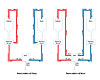
Figure 1. Two Options for Recirculating Filled Two-Component Materials
Recirculating Valves
An effective method of preventing filled two-component materials from separating is to keep them recirculating between dispensing cycles. Recirculation usually takes place at either the pump or the meter/mix valve (see Figure 1).In systems where recirculation occurs at the pump, the primary feed lines are bypassed while the components are recirculated through secondary lines, either back to their original tanks or into separate holding tanks. The result is that the fluid left in the main feed line and valve remains stagnant whenever the system is not in operation. In processes that involve long periods of inactivity, this stagnant material can separate within the main feed line and/or inside the meter/mix valve, leading to the maintenance and downtime issues mentioned earlier.
Systems that recirculate the fluids at the meter/mix valve offer a more efficient alternative. A conventional meter/mix valve has just two ports: one inlet port for the epoxy resin or polyurethane polyol, and another inlet port for the epoxy hardener or polyurethane isocyanate. In contrast, a recirculating meter/mix valve has a total of four ports: one inlet port and one return port for the A component on one side of the valve, and separate inlet and return ports for the B component on the other side.
With recirculating meter/mix valve systems, the material feed lines run from the pump to the A and B inlet ports on the valve. The material return lines run from the valve’s A and B return ports back to the original tanks or to separate holding tanks. While the system is dispensing, the meter/mix valve is open to allow the materials to flow through the static mixing nozzle. When the valve closes, the materials are continuously recirculated through the valve and back to their respective tanks, with no dead volume to become stagnant.
In addition to preventing sediment from collecting inside the valve, having recirculation take place at the valve instead of at the pump eliminates pressure buildup in the supply lines that could produce a surge as the valve opens, resulting in an off-ratio mix. Some recirculating meter/mix valve designs also incorporate a snuff-back feature to keep material from dripping or oozing when the valve closes.
Additional Considerations
As with any two-component application, choosing the appropriate mixing nozzle is a critical consideration. Calculating the pressure drop across the nozzle is usually the first step in selecting an appropriate mixer. A pressure drop of between 30-80 psi is considered ideal and results in a good mixing environment.For most two-component materials, a range of nozzle configurations will be capable of producing a satisfactory mix. Mixing nozzle suppliers can help choose the right nozzle for the specific material and application. By eliminating the risk of filled materials separating in feed lines and valves, recirculating meter/mix valve systems ensure a proper mix and minimize maintenance and downtime, resulting in lower costs and higher productivity.
For additional information, contact the author at (401) 431-7072 or tom.muccino@nordsonefd.com, or visit www.nordsonefd.com.


