The fluids used in the adhesives and sealants industry are among the most difficult to handle of any in the main worldwide process industries. Characteristics that make them particularly difficult to handle include:
• High viscosities (typically 1-2,000 Pa.s, or 1,000-2 million cP).
• Often non-Newtonian (viscosity is not constant and varies with shear rate).
• Some must be processed at temperatures close to their solidification/hardening points, where they are close to changing phase from liquid to solid (e.g., hot-melt adhesives).
• Almost all have low thermal conductivities, often intentionally. This makes them particularly resistant to being heated or cooled.
• Their high viscosity requires that they be pumped at high pressures to be moved from A to B, as well as through all required process equipment and process stages.
• To keep them flowing, they must often be processed at temperatures well above ambient.
• Some of the fluids are intended for food-related use; as such, the alloy and non-alloy materials in contact with the fluids must be approved by the U.S. Food and Drug Administration (e.g., gaskets).
• Equipment used can be difficult to clean safely, causing shutdowns and maintenance delays.
• Many fluids processed are susceptible to degradation if “cooked” for too long.
• Controlling the thermal history of a product by avoiding excessive ranges of residence times (and thereby reducing the potential for degradation) becomes more difficult as soon as flow becomes laminar.
• Process lines are often designed to handle a variety of process fluids and flow rates, which adds further complication.
Heating and Cooling
Heating and cooling are key processes in the adhesives and sealants industry, and ones into which most of the above challenges inevitably fall. Many products need to be processed or formed at high temperatures (e.g., within a reactor or mix vessel), but later cooled to facilitate further processing or handling.
Heating may be required to: enable solvents to be flashed off and recovered via devolatilization; reduce product viscosity to reduce energy losses through screens, filters and other equipment; reduce viscosity to optimize belt cooler or underwater pelletizer operation; and heat reactor contents during a pump around to shorten heatup and overall batch processing time. Cooling may be required to: reduce product temperature to enable safe packaging to occur; reduce temperature and increase viscosity after reactor to optimize belt cooler or underwater pelletizer operation; and reduce temperature before product extrusion.
In the adhesives and sealants industry, indirect heat is most commonly sourced from thermal oil provided from a stand-alone package or a central boiler system if thermal oil is used in other parts of the plant. The thermal oil is heated using gas or electric heaters.
Typical coolants are thermal oil (with its temperature set below the target cooled product temperature) and tempered water. Cold water is rarely used because many products in this industry have solidification temperatures higher than typical mains or cooling tower water temperatures. In addition, the danger of water being vaporized into steam exists if its flow is insufficient to prevent its temperature from rising to above its flash point at operating pressures (100°C or 212°F at atmospheric pressure).
In cooling applications, the thermal oil returns from the heat transfer device hotter than when it was fed to it. At some point, it will be necessary to cool the oil; for this purpose, a plate heat exchanger is connected to the hot oil feed tank using water as a coolant. It is important to remember that this device will need to remove the same amount of heat from the oil as is being removed from the product.
Theory
To be able to make decisions about how to solve heating or cooling problems, it is necessary to understand the basic theory of indirect conductive and convective heat transfer and how it relates to the design of indirect heat transfer equipment. The first key equation, which identifies the magnitude of the heating or cooling challenge, is:
Q = m*Cp*ΔT
where Q = heat addition or removal required (kW, Btu/hr), m = mass flow of the process fluid (Kg/s, lbs/sec), Cp = specific heat of the process fluid being heated or cooled (J/kg K, Btu/lb ºF), and T = required temperature increase or decrease of the process fluid (K or ºF).
The second key equation, which relates the magnitude of the heating or cooling challenge to the heat transfer device you plan to use and to the heat transfer fluid, is:
Q = U*A*ΔTLM
where Q = heat addition or removal required (kW, Btu/hr) – from Equation 1, and U = heat transfer device global coefficient of heat transfer (W/m2 K, Btu/hr ft2 ºF). This is a key factor because it defines the ability of a certain heat transfer device to transfer a certain number of Watts or BTUs per m2 or ft2 of heat transfer surface area per degree K or °F temperature differential. In addition, A = surface area available for heat transfer (m2, ft2) and ΔTLM = log mean temperature difference between the process fluid and the heating or cooling fluid (the “driving force,” K or °F).
The Q in equation 2 is the same Q as in equation 1. Armed with the value of Q determined from equation 1 and the temperature of the available heat transfer medium (e.g., oil, water, steam), which allows calculation of ΔTLM, it is then a question of rearranging Equation 2:
Q/ΔTLM = U*A
It is then necessary to determine which heat transfer device (U) and with which surface area for heat transfer (A) will solve the problem. This process does require purpose-designed software that has the ability to handle multiple variables and to allow rapid optimization.
In Practice
The general objective is now to maximize the heat transfer device (U) and thus minimize heat transfer A. This will lead to the smallest physical heat transfer device and the lowest cost.
One of the most common devices used in heating and cooling applications in the adhesives, sealants, polymer and resins industries is the static mixer heat exchanger. This device is a modified shell and tube heat exchanger that is adapted to the needs of the adhesives and sealants industry. Inlet and outlet heads can be designed to minimize inventory and dead areas, to be jacketed to prevent cold spots and local hardening of process fluids, to provide smooth transitions to customers’ piping, and to be fitted with tapping for thermocouples or pressure transducers.
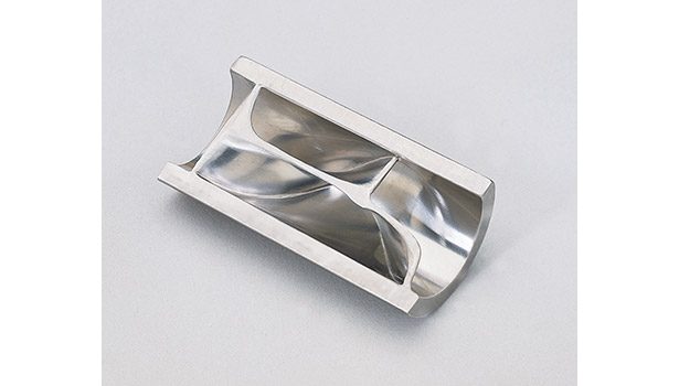
Each tube is filled with static mixer elements to prevent any possibility of process products shortcutting the heat transfer surfaces and to disrupt typical empty tube flow patterns. The continuous radial mixing of the process fluids passing down each tube ensures higher convection of heat to/from the heat transfer surfaces compared to an empty tube design while avoiding extreme thermal gradients and thus burning/freezing (see Figure 1).
Mixing elements can be brazed into the tubes over their entire length to provide further enhanced heat transfer via an internal fin effect. This technique also has the benefit of creating a strong structure that is able to take extremely high compressive loads in high-viscosity applications. Mal-distribution of flow across different static mixer tubes can be avoided through the careful balancing of process side pressure drop against local pressures and also by careful design of inlet/outlet heads. The overall effect of the addition of static mixer elements to the tubes (in addition to the general design optimization processes to be discussed next) is to reduce surface area and internal volume by 2-10 times compared to empty tube designs, to reduce average residence time (hold up) by the same amount, reduce burning/freezing, avoid bypassing, improve product thermal homogeneity and minimizing maldistribution.
Optimizing the Design
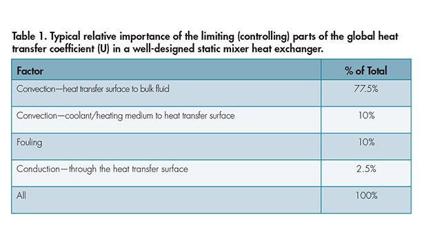
Putting aside the physical properties of the process fluid, which will be the same for all heat transfer devices, the heat transfer device global coefficient of heat transfer (U), which we are aiming to maximize, is predominantly limited by four factors, in decreasing order of importance:
1. Rate of convection of heat from the hot (or to the cold) surface to the bulk process fluid.
2. Rate of convection of heat from the hot heat transfer fluid to the separating surface (or from the separating surface to the cold heat transfer fluid).
3. Degree of fouling of the process or thermal fluid side heat transfer surfaces.
4. Rate of conduction of heat from the bulk hot thermal fluid side through to the cold process fluid side (or vice versa, in the case of cooling) through the separating surface.
A quantification of the relative importance of these controlling factors in a typical static mixer heat exchanger design is given in Table 1. In practice, fouling can be kept small as long as heat transfer fluids are filtered and changed according to the manufacturer’s recommendations, the heat exchanger is designed to maximize turbulence through the correct choice of heat transfer fluid flow rate, baffle design and positioning, and as long as the process fluid is not allowed to accumulate for long on any heat transfer surfaces where it could be degraded and carbonize.
The heat transfer surface thickness would normally be as thin as possible after taking into account mechanical design needs such as pressure retention and cyclic loads. This process ensures that this factor does not significantly affect the global heat transfer coefficient. Convection of heat from/to the heat transfer surface to/from the heat transfer fluid can be maximized; therefore, its influence on overall design is minimized by optimizing fluid flow, baffle positions, and baffle design.
The biggest impact in maximizing U comes from improving rates of convection from the heat transfer surface to the bulk. In a static mixer heat exchanger, this can be achieved by:
• Using the smallest possible static mixer tube bore (sizes down to 3 mm/0.125 in. are possible for lower viscosity fluids). Halving the bore typically increases the global heat transfer coefficient by 65% for the same flow rate.
• Using brazed-in-place instead of standard or removable mixing elements increases the global heat transfer coefficient by 30-40%.
• Using less static mixer tubes to increase axial velocity but increasing their length in compensation to maintain the required heat transfer surface.
Multiple Benefits
Understanding the basic chemical engineering theory behind the design of heat exchangers and the processes they are used for is key to their optimization. The use of static mixers in the tubes of shell and tube heat exchangers offers major benefits to adhesives and sealants manufacturers in terms of equipment size, cost, operational flexibility, process control, and product quality.
For more information, contact the author at neil.cathie@nov.com or visit www.chemineer.com.

