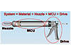
Let’s look at the system by breaking it down into its three basic parts: the nozzle, the material containment unit (MCU) and the drive system (see Figure 1). The nozzle is the device that places the adhesive on the substrate in its desired form. The MCU is the container in which the material is packaged for dispensing, and the drive system is simply the manual, air or cordless drive system used to push the material out of the tool.
Nozzle
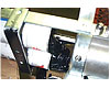
The nozzle is the final piece of apparatus that the material flows through just prior to reaching the intended substrate. Nozzle designs are available in many different shapes, sizes and lengths (see Figure 2). Nozzle design can be a critical issue, and we are all familiar with the various formulas that govern it, including Bernoulli’s equation of fluid flow, Darcy’s formula to calculate heat loss due to friction, Moody’s friction factor and Reynolds numbers, among others.Additional considerations include diameter-to-length ratios, nozzle material properties, how the nozzle reacts with the sealant or adhesive, and post-application issues like cleaning and disposal. However, the real key is flow rate, which relates to the material’s density or viscosity, as well as the dynamic properties of the nozzle. Fluid flow is a direct function of pressure in the MCU. Care must be taken to discover how much pressure should be developed to achieve the application goals, as well as whether the required pressures can be achieved.
Material Containment Unit
The MCU is used to transport material from the manufacturer to the substrate that the material was designed to address. The three most common basic forms of an MCU include cartridge, sausage and bulk. Selecting the right form is important; for example, a large cartridge full of material would not be appropriate if the application is overhead or detailed. Conversely, too small an MCU would be problematic when applying significant volumes of adhesive.The package must fit the application and handle the pressures required to obtain the fluid flow needed through the nozzle. The reactivity of the adhesive or sealant to the package could also be an issue.
Cartridges
In general, 1/10-gal (10-oz) or quart (29-oz) cartridges are the most common for single-component applications. Cartridges are user friendly because the user is never exposed to the adhesive or sealant, and the applications are pretty straightforward. No industry standard currently exists for the maximum pressure containment within the cartridge, so it is important to discuss this issue with your supplier.There are many different plunger designs. Test the cartridge and plunger to ensure that material doesn’t blow past the piston while dispensing. In addition, be careful to not leave the purchasing specifications too open. Manufacturers sometimes inadvertently make changes that turn into problems. For example, buyers might change plungers, which can affect the amount of blow-by material and increase the mess that the end user deals with. Keep in mind that plastic cartridges can swell under extreme pressures, while corrugated cartridges tend to burst under excessive pressures.
Disposability has its benefits and challenges. Filling Dumpsters with empty cartridges at job sites can become an issue and is sometimes prohibited, especially if the material is considered hazardous waste.
Following are the three most common cartridges and some of their attributes for consideration. The corrugated cartridge has a foil skin liner on the inside that can be anywhere from 0.0035 to 0.001 in. thick, with or without poly-coating. The liner is the barrier and the strength of the cartridge; it is what deals with the pressures inside the MCU.
The corrugated composition is either grease-proof or a lardpak paper system. Generally speaking, there are two nozzle sizes-a 3-in. and 4-in. standard spout. The larger, 4-in. spout is generally used with higher-viscosity materials to reduce the pressure within the cartridge. For industrial applications (primarily for detailed adhesive applications), the stub spout cartridge allows users to select from a number of different nozzle sizes.
The poly-HDPE plastic cartridge is ideal for latex, acrylic latex, water-based products, silicones and some MS polymers. The viscosities of these materials are relatively low, so the system comes with a 3-in. nozzle or industrial stub spout. Wall thicknesses are 0.040 to 0.060 in., depending on the material and MCU pressure. Many use a foil pack and/or wax coating at the opening end. Keep in mind that if the MCU pressure is too great, the cartridge could swell and material blow-by could be a challenge unless the plunger is designed to deal with this issue.
The aluminum cartridge, sometimes called a can, is designed for high-viscosity materials that require extreme MCU pressures to achieve fluid flow through the nozzle. Some fast-curing materials also use this package.
Sausage
A sausage is a laminated film sealed around material in a sausage form (generally in 10- or 20-oz volumes). This type of package offers cost savings over cartridges due to the improved speed of the filling process.Keep in mind that it is much easier for a material manufacturer to introduce material in this package to end users who generally deal with material packaged in pails (bulk form) vs. those who have purchased cartridges, because sausages offer less mess than bulk but more mess than cartridges. Mess means exposed adhesive and sealant that the end user must deal with before, during or after the application.
Disposal is an advantage of sausages because the package can be squashed down to a small disc and consumes very little Dumpster space. Transporting and packaging of sausages needs to be taken into account, however. The case needs to be of very strong construction because a sausage can be easily pierced during the transportation process.
Portability can be a plus, especially in the firestop industry. The end user can gather two or three sausages and crawl up through the many obstacles they deal with to apply their material. (It is hard to be effective in this type of environment with bulk material or even cartridges.)
Sausages require a higher-end dispensing tool that essentially supports the sausage’s skin when pressurized. The entire tool design is critical to the success of this system. For example, the piston must push the material out and develop the pressure in the MCU, but also strip the skin off the barrel of the tool without puncturing or pinching the skin.
No industry standards currently exist for the diameter or length of a sausage. Problems arise when the sausage is too large in diameter and it doesn’t fit in a tool, or too small in diameter and the skin isn’t supported by the tool. GO and NO/GO gauges have been developed in order to begin to establish a standard and to aid in the quality control assurance of sausages during their manufacture.* The GO hole in the gauge will allow the sausage to pass through with little to no resistance, while the NO/GO hole does not allow the sausage to pass through. Many material manufacturers use these gauges as a “standard,” and the diameter issues surrounding sausage manufacturing have dropped significantly as a result.
Bulk
Pails (2- and 5-gal) are clearly the least expensive method (per ounce) of supplying material to the market. This form of material containment requires a customer base that is familiar with the issues surrounding bulk material and loading and unloading a dispensing tool. Depending on its viscosity, the material can be transferred from the pail to the MCU of the tool by drawing it into the tool through suction, or pumping it into the tool with a caulking loader.Some materials, such as those that are silicone based, also skin quickly when exposed to the air or moisture. In that case, follow plates are used to reduce the exposure to the elements. In addition, tools must be designed to handle the material, be resistant to the chemicals it will be exposed to, and generate the suitable pressure to the MCU with an acceptable end user effort.
Drive System
Drive systems essentially generate the force that, in turn, generates pressure inside the MCU and thus the flow rate through the nozzle. When looking at force, pressure and flow rate, we go back to a basic physics equation:Force = Pressure x Area (F = PA)
For our purposes, this equation can be converted to Pressure (the pressure in the MCU) equals Force (force generated by the drive system) divided by the Area (cross-sectional areas of the MCU, which happens to equal the area of the piston):
P = F/A
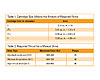
If the same pressure is needed to obtain the same flow rate, and the cartridge size is changed from a 1/10th gal to a quart, the MCU diameter essentially goes from 17/8 in. to 25/8 in., doubling the cross-sectional area and requiring at least double the force. What isn’t discussed is the fact that the nozzle sizes are the same, so the drive system is pushing material against a larger wall (flat surface of the cartridge). That alone consumes some energy and raises the pressure in the MCU to obtain the same flow rate (see Table 1, p. 20).
Drive systems are available in three categories-manual, air and battery.
Manual Drives
Manual drives, which are generally inexpensive and easy to operate, are available in two different styles: continual flow or drip-less (also called drip-free). As you might expect, the continual flow provides a more continual, even flow down the substrate while the drip-less option is more of a spot application-type tool.Unique to manual drives is the fact that the user is the mechanism by which energy is drawn; this can vary depending on the individual. Using a 20- to 30-year-old male who generates 100 lbs of average force between his third and fourth fingers as our “standard,” thrust can be generalized.
Determining the proper amount of thrust is similar to riding a bike-you want to be in a high gear on the straight-away to get the maximum flow (standard caulk gun), and you down-shift to a low gear when going up a hill (high-thrust drive). You don’t want a high-thrust drive when dispensing low-viscosity material, and vice versa.
Figure 3 shows how cartridge diameter, pressure and forces relate and where the different drive systems fit on the graph. Using this graph, along with the length of material bead and a ½-in. nozzle per trigger squeeze, users can determine how the specific system related to their material may work. It might be necessary to go back to the lab and reformulate the material to reduce or increase the viscosity, which, in turn, may change the system results.
Air-Powered
Air-powered drives are unique in that there is no force vector. Generally speaking, the air pressure is the pressure inside the MCU, and this brings different issues to the table:• The max pressure in the MCU is the max air pressure available (i.e., it could be 100 psi and that is all).
• The size or diameter of the MCU is no longer an issue because the pressure doesn’t change.
• Cartridge design is important because most cartridge plungers are not designed for pressurized air. Therefore, air may enter the material side of the MCU.
• Pressurized air is essentially a coil spring. If the cartridge or cap is not properly assembled to the tool, then the unit may launch the MCU like a missile.
• Air tools have infiltration issues: water is generated when compressing air, and dust and dirt can be sucked into a compressor. All of these must flow through the air gun and can periodically cause problems.
Battery-Powered
Cordless drives are a continuous moving device; when the motor is turned on, the piston rod moves forward at a set rate. These drives are very linear and have little regard for the pressure they develop. Most units have maximum force limitations but, until those limitations are reached, the unit will function linearly regardless of the pressure it develops.It is important to note that, regardless of the type of drive system, if the cartridge has a burst pressure of less than what the drive system provides, there is a high probability of failure in the field. This is because users try to purge clogged nozzles using the drive system and pressure in the MCU, thereby over-pressurizing the MCU.
Two-Component Applications
Two-component materials can be dispensed in two basic ways: by premixing the material and using a bulk single-component tool, or using two-component, double-barrel cartridges or sausages. Generally speaking, the premixed, single-component bulk gun is used when significant volume or coverage is required and the cure time is long. When using two-component cartridges or sausages, the rate of flow is slower and it demands more of the drive system.Cartridge and sausage applications require a nozzle, called a static mixer, which mixes the material. Note that the A and B material are mixed together as they pass each element, and each mix raises the pressure required in the MCU to obtain fluid flow. Many different sized cartridges (MCUs) and static mixing nozzles are available. When developing your system, it is important to keep the following in mind:
• Material compatibility. At least two different materials are used in the construction of the cartridges.
• Piston design is critical for storage leakage, and moisture infiltration can become an issue.
• Solid settling. It is very important that the fluid is of consistent viscosity during the mixing process. If solids settle during storage and the viscosity of the material inside the MCU is different through the cartridge, flow rates and reactive rates can and will be an issue.
• P = F/A and flow rates are much more sensitive due to the pressures required to obtain flow rates through the static mixer. A larger diameter and fewer required mixing elements will make a big difference in the pressure required in the MCU. In addition, with higher pressures required for suitable flow rates, the system is very area-sensitive when calculating the forces.
• Air-driven tools are designed differently in order to increase the forces required to dispense two-component cartridges. Figure 4 shows that the pressure within the MCU equals the force of the drive system divided by the area of the cartridges. However, the force of the drive system also equals the pressure within the air gun divided by the piston area of the drive system. This enables us to use 120 psi of air and generate more force and pressures in the MCUs.
Key Points
For both single- and two-component materials, it is vital to develop the sealants and adhesives before the application system. Additional important factors to keep in mind include:• The nozzle design determines how the material is applied to the intended substrate(s).
• The flow rate through the nozzle determines the necessary pressure within the MCU. The MCU must be able to contain that pressure without failure and transport material to the intended application.
• The basic P = F/A formula helps determine the right size MCU and drive system.
• Two-component materials are far more complicated and require significantly more time to design the right system for the application.
• Before the system is complete, the adhesive or sealant design may have to be modified.
About the Company
Albion Engineering Co. has been in existence since the late 1800s. The company was purchased by F. Karl Schneider in 1929 and entered the dispensing tool arena with Schneider’s first patent in 1933. Since then, Albion has been working with the evolution of tools and packages through three generations. The company works intensely with both packaging organizations and material manufacturers to develop solutions that ease the challenges of bringing new products to market.For additional information, contact Albion Engineering Co. at 1250 Church St., Moorestown, NJ 08057; (856) 235-6688; fax (856) 235-9460; e-mail service@albioneng.com; or visit www.albioneng.com.
*These gauges have been developed by Albion Engineering Co. and can be provided to material manufacturers at no charge, upon request.
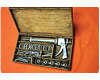
SIDEBAR: A Little History
1894: The first caulking gun patent was issued.1933: Albion Engineering Co. developed and patented the first smooth rod drive dispensing tool.
1940s: Material manufacturers introduced cartridges in many different sizes and shapes. The material manufacturers sold the entire system (cartridge plus the gun). As time progressed, the 1/10-gal cartridge and the quart cartridge became standard.
1980s: Single-component sausage packaging was introduced to the market.
1990s: Two-component cartridges with static mixing nozzles were introduced to the market and evolved.
2000s: Two-component cartridges with static mixing nozzles were introduced that fit into a standard single-component dispensing tool.